

UFS (Universal Flash Storage) has become an important high-performance storage solution in smartphones, automotive electronics, industrial computing, and other embedded systems. As UFS devices continue to increase in capacity and complexity, programming them requires more than simply transferring a firmware image to a memory chip. Engineers must also understand logical unit configuration, boot-related settings, security-sensitive storage areas, and device-specific parameters.
A UFS programmer provides the hardware and software interface needed to configure, read, write, and verify supported UFS memory devices. However, the available functions can vary significantly between programmer models. Some focus on basic data programming, while engineering-oriented solutions may also provide access to descriptors, attributes, flags, LUN configuration, and RPMB-related operations.
This guide explains the major UFS storage structures and configuration functions, how they relate to the programming process, and what engineers should evaluate when selecting a UFS programmer. Whether you are developing a new electronic product, preparing memory devices for manufacturing, or establishing a repeatable programming workflow, understanding these functions can help reduce configuration errors and improve production consistency.
- 1. Understanding UFS Storage Architecture
- 2. What Is LUN Configuration in UFS Programming?
- 3. Understanding UFS Boot Areas and Boot Configuration
- 4. What Is RPMB and Why Does It Matter?
- 5. UFS Descriptors, Attributes, and Flags Explained
- 6. UFS Chip Programming: A Step-by-Step Workflow
- 7. Common UFS Programming Problems and Troubleshooting
- 8. How to Choose the Right UFS Programmer
- 9. UFS Programming Solutions for Modern Manufacturing
- 10. Conclusion
1. Understanding UFS Storage Architecture
Before configuring a UFS device, it is important to understand how its storage resources are organized. Unlike a simple memory chip that exposes one continuous storage area, UFS uses a structured architecture with multiple logical units and configuration information. These components determine how the host system accesses data and how the device behaves during initialization and operation.
1.1 What Makes UFS Different from Conventional Flash Storage?
UFS is a managed NAND flash storage solution that integrates a controller, NAND memory, and a standardized host interface. The controller manages internal flash operations, including logical-to-physical address mapping, error correction, and wear management. The host communicates with the device through the UFS interface rather than directly controlling raw NAND operations.
This architecture makes UFS suitable for systems that require high data throughput, efficient power management, and reliable storage access. It also means that programming must account for the device's logical organization and configuration parameters instead of treating the chip as an ordinary raw flash component.
1.2 User LUNs and Well-Known LUNs
UFS logical units are not all the same type. The specification distinguishes between User LUNs, which provide general-purpose data storage, and Well-Known LUNs (W-LUNs), which provide access to special device functions rather than ordinary user data. Understanding this distinction is essential before assigning images or configuration data to a logical unit.
| Logical Unit Type | Purpose | Programming Relevance |
|---|---|---|
| User LUN | General data storage. The available capacity can be divided among user LUNs according to the device configuration. | Firmware images and user data are typically programmed to user LUNs according to the partition map. |
| Boot W-LUN | Provides a boot-related access mechanism and is associated with the configured Boot Logical Units (Boot LU A / Boot LU B). | Used to access boot-related data during device programming and platform startup. |
| RPMB W-LUN | Provides access to replay-protected storage through an authenticated access mechanism. | Requires security-aware provisioning and authenticated transactions; not ordinary user storage. |
The practical implication is important: Boot and RPMB are not simply additional user data LUNs. They are well-known logical units with dedicated access mechanisms, so their programming and configuration requirements differ from ordinary user LUNs. Other descriptor and unit structures, described later in this guide, complete the picture of how a UFS device organizes its storage resources.
1.3 Why Storage Architecture Matters During Programming
When a programming project involves UFS memory, the firmware image is only one part of the overall configuration. Engineers also need to determine which logical unit should receive each image, whether the boot-related settings match the target system, and whether any security-related operations are required.
For example, writing a system image to the wrong LUN may result in a device that can be detected by a programmer but cannot operate correctly in its intended application. Similarly, an incorrect boot configuration may prevent the host processor from loading the expected startup code. This is why programming verification should cover both the written data and the relevant device configuration, a point that is developed further in the workflow and troubleshooting sections below.
2. What Is LUN Configuration in UFS Programming?
LUN stands for Logical Unit Number. In UFS, a logical unit is an independently addressable storage unit presented by the device to the host. A single UFS device can contain multiple LUNs, allowing storage resources to be organized for different system functions.
For engineers working with a UFS programmer, LUN configuration is one of the most important steps because it determines how available storage capacity is divided and how programming data is assigned to individual logical units.
2.1 How UFS Logical Units Work
A UFS device may expose several logical units, each identified by a logical unit number. Depending on the device design and configuration, these units can serve different purposes, such as storing operating system data, application data, or other system resources.
Logical units are not necessarily separate physical NAND chips. They are logical storage structures managed by the UFS controller. The controller handles the underlying physical flash management while presenting the configured logical units to the host.
2.2 Common LUN Configuration Parameters
When configuring a UFS programming project, engineers may need to review the following parameters, depending on the device and programmer software:
- LUN ID: Identifies an individual logical unit within the UFS device.
- LUN capacity: Defines the available storage capacity assigned to a logical unit.
- Logical block size: Determines the unit used for logical data addressing.
- Allocation units: Provide the basis for configuring the size of a logical unit through device-specific parameters.
- Provisioning settings: Determine how storage resources are allocated and exposed by the device.
2.3 Illustrative UFS Storage Layout
The following table shows how a configured UFS device might organize its logical units in a typical embedded application. It is a conceptual illustration only: the actual LU count, capacity, and boot configuration depend on the specific UFS device and its configuration.
| Logical Unit | Typical Role |
|---|---|
| User LU 0 | Operating system and system data. |
| User LU 1 | Application and user data. |
| Boot LU A / Boot LU B | Boot-related storage, when the boot feature is configured. |
| RPMB W-LUN | Authenticated, replay-protected storage for security-sensitive data. |
Conceptual illustration only. Actual LU count, capacity, and boot configuration depend on the UFS device.
2.4 How to Configure LUNs Correctly
A typical LUN configuration process involves several checks:
- Detect the UFS device: Establish communication between the programmer and the target chip.
- Read the device information: Retrieve the relevant descriptors and identify the logical units supported by the device.
- Review the required storage layout: Compare the intended LUN structure with the target product's system requirements.
- Calculate the required capacity: Confirm that the configured allocation units do not exceed the device's available resources.
- Apply the supported configuration: Use the programmer software to configure the logical units where the device and tool permit it.
- Verify the resulting layout: Read back the relevant configuration information and confirm that the device exposes the expected logical units.
2.5 Common LUN Configuration Mistakes
| Problem | Possible Cause | Recommended Check |
|---|---|---|
| Incorrect LUN capacity | Allocation values do not match the available device capacity. | Recalculate the allocation units and review device geometry. |
| Missing logical unit | The target configuration does not expose the expected LUN. | Check the configuration descriptors and device support. |
| Image written to the wrong LUN | Incorrect partition mapping in the programming project. | Confirm the image-to-LUN assignment before programming. |
| Configuration write failure | Unsupported settings, configuration restrictions, or device state. | Check the device specification and programmer compatibility. |
It is also important to understand that changing a UFS configuration descriptor can have destructive consequences. Depending on the operation, existing logical unit data may be formatted or become inaccessible. Always back up required data and confirm the intended configuration before applying changes.
3. Understanding UFS Boot Areas and Boot Configuration
Boot configuration is another important aspect of UFS programming. In embedded systems, the storage device must provide the data required by the host processor during startup. If the expected boot information is missing, incorrectly programmed, or associated with an incompatible configuration, the system may fail to initialize.
3.1 What Is a UFS Boot Logical Unit?
UFS supports boot-related functionality through designated boot logical units. The device may provide Boot LU A and Boot LU B, and the boot LU is selected through device configuration, allowing the host system to access the appropriate startup data during the boot process.
It is important not to confuse a UFS boot logical unit with eMMC Boot1 and Boot2 partitions. Although both storage technologies provide boot-related functions, their internal configuration mechanisms and terminology are different.
3.2 Understanding the Boot Configuration Parameters
UFS boot behavior is controlled by several configuration items that work together. The most relevant fields include:
| Configuration Parameter | Function |
|---|---|
| bBootEnable | Enables or disables the UFS boot feature. |
| bLUEnable | Enables or disables the corresponding logical unit. |
| bBootLunID | Designates a logical unit as Boot LU A or Boot LU B. |
| bBootLunEn | Selects which Boot LU is currently enabled and presented to the host. |
Note that boot configuration involves the Configuration Descriptor, the unit configuration entries for the relevant logical units, and the related device attributes. Enabling a single field is not sufficient on its own: the LU that serves as the boot LU must also be enabled and configured, and bBootLunEn must select the intended Boot LU. After the configuration is written and committed, the device typically needs to be re-initialized or reset before the updated logical unit configuration takes effect. The exact requirements should always be checked against the target UFS specification version and the platform's boot documentation.
3.3 A Practical Boot Programming Checklist
- Confirm that the target UFS device supports the required boot functionality.
- Configure all related items consistently: bBootEnable, bLUEnable, bBootLunID, and bBootLunEn.
- Check that the boot image matches the target processor and platform.
- Commit the configuration and re-initialize the device so the updated boot LU selection takes effect.
- Verify the written data and relevant configuration parameters after programming.
- Perform a system-level startup test when the programmed device is integrated into the target hardware.
3.4 Why Boot Configuration Errors Are Difficult to Diagnose
A UFS chip may respond to a programmer and pass basic data verification while still failing to boot in the final product. This is because a successful memory write only confirms that the intended data was transferred and verified at the selected storage location. It does not necessarily validate the complete boot chain, including the boot LU selection and the host-side startup process.
For this reason, engineers should distinguish between memory-level verification and system-level validation. Both are necessary when preparing UFS devices for embedded applications.
4. What Is RPMB and Why Does It Matter?
RPMB stands for Replay Protected Memory Block. It is a security-oriented storage area designed to protect data against unauthorized modification and replay attacks. Unlike ordinary user storage, RPMB is accessed through a well-known logical unit with an authenticated access mechanism and a write counter to help ensure the integrity of stored information.
RPMB is relevant in systems that handle sensitive information, including security-related metadata, trusted application data, and other protected records. Its operation requires more careful handling than ordinary UFS user data.
4.1 How RPMB Differs from Normal UFS Storage
| Feature | Normal UFS User Storage | RPMB |
|---|---|---|
| Primary Purpose | General-purpose data storage. | Protected storage for security-sensitive information. |
| Access Control | Managed through normal UFS access mechanisms. | Uses authenticated access mechanisms. |
| Replay Protection | Not provided as an inherent feature of ordinary user-area writes. | Uses a monotonically increasing write counter and authentication. |
| Programming Requirements | Standard data writing and verification workflows. | Security-aware provisioning and authenticated transactions. |
4.2 The Role of Authentication in RPMB
RPMB operations rely on message authentication codes (MACs) to validate authorized requests. A shared secret key is used as part of the authentication process. The device also maintains a write counter to help prevent previously valid write requests from being replayed.
This mechanism means that RPMB cannot be treated as an ordinary storage partition. A programmer may support RPMB-related functions such as reading information, displaying status, or performing supported authenticated operations, but the available functionality depends on the programmer, device, and security provisioning state.
4.3 RPMB Programming Considerations
Before performing RPMB-related operations, engineers should consider the following:
- Key provisioning: Determine whether the RPMB authentication key has already been programmed and whether the device permits the intended provisioning operation.
- Authentication requirements: Confirm that the programmer or host software supports the required authenticated transactions.
- Write counter: Understand how the device manages the write counter and how it affects subsequent operations.
- Security policy: Follow the product's security architecture and key-management procedures.
- Tool compatibility: Confirm that the selected programmer supports the required RPMB operations for the target UFS device.
4.4 Why RPMB Requires Extra Caution
• Perform key provisioning only in a controlled, security-managed environment.
• Verify the target device identity and the key source before writing the key.
• Never treat the RPMB key as ordinary programming data.
• Establish a dedicated key-management and verification process on the production line.
Beyond key provisioning, RPMB operations should be planned and validated before production. Using an incorrect key, an unsupported transaction, or an inappropriate provisioning sequence can make the protected storage unusable for the intended application. Security keys should be handled through controlled provisioning procedures rather than embedded casually in general programming projects.
5. UFS Descriptors, Attributes, and Flags Explained
Descriptors, attributes, and flags provide important information about the UFS device and its configuration. These are three different kinds of configuration objects, and a UFS programmer that supports access to them gives engineers more visibility into device characteristics and allows them to perform certain configuration tasks beyond basic data writing.
5.1 UFS Descriptors
Descriptors contain structured information about the UFS device and its logical units. Different descriptor types provide information about different aspects of the device. Common descriptor types include:
- Device Descriptor: Contains general, read-only device-level information, including configuration-related fields such as the number of available logical units.
- Configuration Descriptor: Contains the device's configurable parameters, including boot-related settings and the per-LU unit configuration entries.
- Unit Descriptor: Provides information about individual logical units, including their type and configuration.
- Geometry Descriptor: Describes storage geometry and related capacity characteristics.
- Interconnect Descriptor: Describes the interconnect layer and its characteristics.
- Power Descriptor: Describes device power behavior and supported operational modes.
- Health Descriptor: Provides device health-related information where supported.
- RPMB Unit Descriptor: Provides information related to the RPMB logical unit.
Reading descriptors helps engineers understand the target device before writing data or changing its configuration. It is particularly useful when working with different UFS capacities or device models. Note that the Device Descriptor primarily exposes read-only information, while the Configuration Descriptor contains the parameters that can be modified through a supported configuration sequence.
5.2 UFS Attributes
Attributes represent device parameters that can be read and, where supported, modified through defined UFS operations. They may relate to device behavior, operational settings, and other configurable characteristics.
For example, certain reference clock and power-related attributes can influence device operation. However, not every attribute is writable, and some fields may have restrictions depending on the UFS specification version or device implementation.
5.3 UFS Flags
Flags generally represent status or control information that can be read or modified according to the applicable UFS command definitions. They may be used to enable or indicate specific device functions.
When using a programmer, engineers should review the supported flag operations and understand whether a change is reversible, persistent, or subject to device-specific restrictions. Fields such as fDeviceInit should always be handled according to the read/write permissions and operating conditions defined by the target UFS specification version.
5.4 Descriptors, Attributes, and Flags: Concrete Examples
| Parameter Type | Example | Purpose |
|---|---|---|
| Descriptor | Device Descriptor | Read device-level information such as vendor, model, and available logical units. |
| Descriptor | Configuration Descriptor | Read and modify configurable device parameters, including boot and LU settings. |
| Attribute | bBootLunEn | Select which Boot LU is currently enabled. |
| Flag | fDeviceInit | Indicates the device initialization status and is used to trigger device initialization. |
Keeping these object types distinct matters in practice: a descriptor is read (and, in the case of the Configuration Descriptor, written through a defined configuration sequence), an attribute is read or set through attribute operations, and a flag is toggled or read through flag operations. A useful UFS programming workflow should review the relevant information before applying changes and verify the resulting values afterward, using the correct operation type for each object.
6. UFS Chip Programming: A Step-by-Step Workflow
A reliable UFS programming process should combine device detection, project configuration, configuration commit, data writing, and verification. The exact software interface and available commands depend on the programmer, but the general engineering workflow follows a similar structure.
6.1 Step 1: Prepare the UFS Device and Programming Hardware
First, identify the target UFS device and confirm that the selected programmer supports its model, capacity, interface generation, and package type.
For socket-based programming, use the correct socket adapter and ensure that the chip is positioned properly. Inspect the contacts and fixture for contamination or damage. For production environments, stable mechanical contact is essential for consistent results.
6.2 Step 2: Connect the Programmer and Detect the Device
Connect the programmer to the host computer and launch the corresponding programming software. Select the appropriate device or algorithm and initiate device detection.
At this stage, the software should establish communication with the UFS chip and retrieve the supported device information. If detection fails, check the socket connection, power supply, communication interface, and device compatibility before proceeding.
6.3 Step 3: Read and Review Device Configuration
After successful detection, review the device descriptors, attributes, flags, and available logical units where supported.
This step helps identify the current device configuration and prevents engineers from applying an incorrect programming project to an incompatible chip.
6.4 Step 4: Load the Programming Image
Load the required firmware or data image into the programming software. Confirm that the file format, image size, and target storage location are compatible with the selected device.
For projects involving multiple logical units, verify the mapping between each image file and its intended LUN. Do not assume that the image file name alone guarantees the correct storage destination.
6.5 Step 5: Configure the Programming Job
Configure the required operations according to the project specifications. A typical job may include:
- Device detection and identification.
- Required device configuration operations.
- Image loading and logical unit mapping.
- Data programming.
- Checksum or data verification.
- Additional supported configuration operations where necessary.
The operation sequence should be determined by the target device and programming software documentation. Some configuration changes may need to take place before data writing, while others may be performed afterward.
6.6 Step 6: Execute the Programming Process
Start the programming job after checking the device, image, and configuration settings. Monitor the software status and error messages throughout the process.
When the job includes configuration changes, confirm that the configuration commit completes successfully. The device should accept the new configuration; a commit that silently fails can leave the device with the old configuration even though the write operation appeared to succeed. Check the programming software's status output or read back the configuration descriptor to confirm that the device has accepted the changes.
During production, avoid unnecessary interruptions to power or communication. A stable power supply, suitable programming fixture, and controlled operating environment can help reduce inconsistent programming results.
6.7 Step 7: Re-initialize and Verify the Configuration
After a configuration commit, the device generally needs to be reset or re-initialized before the updated logical unit configuration takes effect. Re-detect the device and read back the relevant descriptors to confirm that the device now exposes the expected logical units and settings. If the configuration has not taken effect, re-check the commit status and the device's supported configuration sequence before continuing.
6.8 Step 8: Verify Programming Results
Depending on the software and device support, verification may include:
- Checking the programming completion status.
- Performing checksum comparison or data read-back verification.
- Confirming that the expected logical units are available after re-initialization.
- Reviewing relevant descriptors, attributes, and flags.
- Checking boot-related configuration where required.
- Performing application-level testing when the device is installed in the target system.
6.9 Step 9: Record the Results for Quality Control
For repeatable production, record important programming information such as device identification, project version, image version, programming status, verification results, and failure codes.
These records help engineers trace production issues and compare results across different programming batches. When integrated with manufacturing execution systems, programming records can also support broader process traceability.

7. Common UFS Programming Problems and Troubleshooting
UFS programming problems can occur at different stages, from initial device detection to data writing and final verification. Understanding the possible causes makes troubleshooting more efficient and helps prevent repeated failures in production.
7.1 UFS Device Cannot Be Detected
Possible causes:
- Incorrect socket adapter or incompatible package support.
- Unstable power supply or insufficient operating power.
- Poor contact between the chip and socket.
- Unsupported UFS device or firmware revision.
- Incorrect software or programmer configuration.
Recommended actions: Check the physical connection, verify the power supply, confirm device compatibility, and ensure that the correct software and firmware versions are installed.
7.2 LUN Configuration or Programming Failure
Possible causes:
- Incorrect allocation unit calculation.
- Image-to-LUN mapping errors.
- Unsupported logical unit configuration.
- Configuration restrictions imposed by the device.
Recommended actions: Read the current unit descriptors, compare the configured storage layout with the device specification, and verify the capacity calculation before applying configuration changes.
7.3 Data Verification Failure
Possible causes:
- The programming image does not match the intended target data.
- Communication instability during writing or read-back.
- Incorrect storage address or LUN selection.
- Device-related hardware or media errors.
Recommended actions: Check the source image, confirm the storage destination, inspect the socket connection, and repeat the operation using a known-good configuration when appropriate.
7.4 Boot Failure After Successful Programming
Possible causes:
- Incorrect boot logical unit configuration.
- Boot image incompatibility with the target platform.
- Incorrect boot-related descriptor settings.
- Missing or incompatible system initialization data.
Recommended actions: Review the boot configuration and verify the image against the target platform requirements. If the storage-level checks pass, continue with host-side boot-chain diagnostics.
7.5 RPMB Operation Failure
Possible causes:
- Authentication key mismatch.
- Incorrect authenticated transaction parameters.
- Write counter or security-state restrictions.
- Programmer software that does not support the required RPMB operation.
Recommended actions: Check the RPMB provisioning state, confirm the authentication procedure, and follow the device manufacturer's security documentation. Avoid repeated experimental writes to a security-protected area.
7.6 Quick Diagnostic Reference
The following table summarizes additional diagnostic checks that are worth performing for common failure symptoms, beyond the general causes listed above:
| Failure Symptom | Additional Diagnostic Check |
|---|---|
| Device detected but a LUN is missing | Check the configuration descriptor and the LU enable state (bLUEnable) for that logical unit. |
| Boot image written but the device cannot boot | Check the Boot LU mapping (bBootLunID, bBootLunEn) and the platform's boot selection settings. |
| RPMB authentication failed | Check the key provisioning state and how the MAC is being generated for the transaction. |
| Configuration changes not taking effect | Check the configuration commit status and re-initialize the device before re-reading the configuration. |
7.7 How to Reduce Repeated Programming Failures
A preventive approach is usually more effective than troubleshooting failures after they occur. Manufacturers should establish standardized programming projects, validate images before production, maintain compatible hardware and software versions, and use repeatable verification procedures.
It is also useful to classify failures by stage, such as detection, configuration, programming, verification, or system boot. This makes it easier to identify recurring issues and determine whether they originate from hardware, software, device configuration, or the production process.
8. How to Choose the Right UFS Programmer
Choosing a UFS programmer requires more than comparing advertised programming speeds. The right equipment should match the target memory devices, programming operations, production volume, and quality requirements of the application.
8.1 UFS Generation and Device Compatibility
Start by checking whether the programmer supports the UFS generation used in your project. Compatibility should be confirmed at the device-model level rather than inferred from a general UFS version label.
Also consider package support, capacity range, supported device vendors, and whether the programming software provides the required device algorithms.
8.2 Support for Advanced UFS Configuration
If your project requires more than basic image writing, evaluate whether the programmer supports the relevant advanced functions.
- LUN configuration and storage layout management.
- Descriptor reading and supported configuration operations.
- Attribute and flag access.
- Boot-related configuration.
- RPMB operations where required.
- Data verification and programming logs.
These functions should be checked individually. A product description that mentions UFS programming does not automatically mean that every advanced configuration feature is available.
8.3 Programming Speed and Throughput
Programming speed affects production efficiency, especially when large UFS images are written repeatedly. However, advertised maximum speed is only one part of the evaluation.
Actual throughput can depend on the UFS device, image size, host computer, interface, programming algorithm, verification settings, and number of active programming sites.
When comparing equipment, request performance data using a representative device and programming image. It is also useful to distinguish between raw data transfer speed, effective programming speed, and total cycle time.
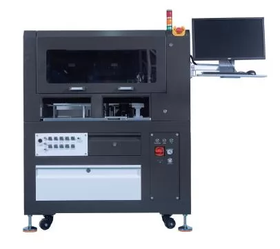
8.4 Manual, Offline, and Automated Programming
Different production stages require different programming approaches. Manual equipment can be suitable for engineering development and smaller batches, while offline and automated systems can better support repeatable high-volume operations.
| Programming Type | Typical Application | Key Evaluation Point |
|---|---|---|
| Manual Programmer | Engineering development, verification, and small-batch work. | Ease of operation, device compatibility, and flexible configuration. |
| Offline Programmer | Batch programming of devices before PCB assembly. | Programming speed, socket capacity, and project management. |
| Automated Programming System | High-volume manufacturing and integrated production lines. | Throughput, handling stability, traceability, and system integration. |
8.5 Software and Production Integration
Programming software should make it possible to create, save, and reuse programming projects. For manufacturing environments, additional functions such as batch operation, programming logs, error reporting, and integration with production systems can improve process control.
For larger production lines, consider whether the programmer supports the required communication interfaces, automation commands, or integration methods used by your existing manufacturing equipment.
8.6 Technical Support and Long-Term Compatibility
UFS technology continues to evolve, so long-term support is an important selection factor. Evaluate the supplier's software update policy, device compatibility updates, technical documentation, troubleshooting support, and ability to assist with project-specific requirements.
8.7 UFS Programmer Selection Checklist
| Evaluation Factor | Questions to Ask |
|---|---|
| Device Compatibility | Does it support the target UFS generation, device model, capacity, and package? |
| Configuration Functions | Can it access the required LUNs, descriptors, attributes, flags, and boot settings? |
| RPMB Support | Does it support the specific authenticated RPMB operations required by the project? |
| Programming Performance | What is the actual throughput with the target device and image size? |
| Verification | Does it provide checksum, read-back, and job-status verification? |
| Production Capacity | Does it support the required number of concurrent programming sites? |
| Integration | Can it connect with existing automation and manufacturing systems? |
| Technical Support | Are software updates, documentation, and engineering support available? |
Using this checklist helps buyers compare equipment according to real project requirements rather than relying on a single headline specification.
9. UFS Programming Solutions for Modern Manufacturing
For engineering teams and manufacturers handling high-density memory devices, programming equipment needs to balance speed, device compatibility, operational stability, and production flexibility.
VeloMax develops programming solutions for semiconductor and electronic manufacturing applications. Its product portfolio covers the main programming scenarios, from engineering-stage manual operation to high-volume automated production:
| Product | Positioning | Typical Use Case |
|---|---|---|
| Aerospeed-G3 | UFS 4.1 high-speed programming | High-speed UFS programming with selectable speed gears, suited to performance-driven production. |
| Aerospeed-GS | Manual and flexible programming | Engineering development, verification, and small-batch programming tasks. |
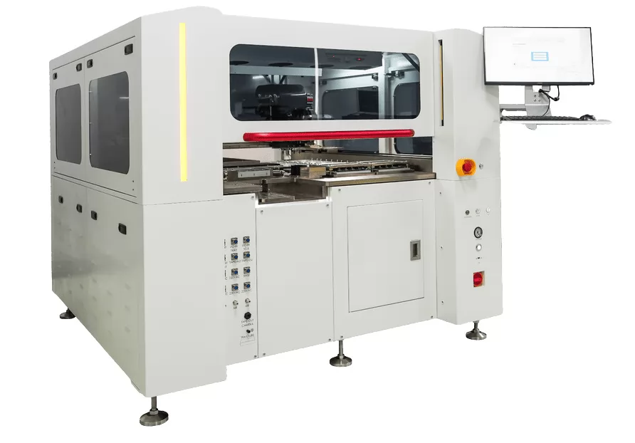
| AST-9000 | High-density automated programming production | Automated programming, inspection, marking, and packaging for UFS, eMMC, and NAND/NOR Flash devices. |
| AST-1000 | Automated programming and production integration | Automated programming with MES integration for connected production lines. |
9.1 Aerospeed-G3: UFS 4.1 High-Speed Programming
The Aerospeed-G3 UFS 4.1 High-Speed Programmer is positioned for high-speed UFS programming applications. According to VeloMax, it is the world's first programmer equipped with UFS 4.1 technology and offers a maximum advertised programming speed of up to 3000 MB/s, making it the flagship option for manufacturers prioritizing programming throughput.
Its selectable speed gears allow users to adjust programming performance according to project requirements. This can be useful for manufacturers evaluating the balance between programming speed, production needs, and operating costs.
For projects involving advanced UFS configuration, buyers should contact VeloMax to confirm the specific supported device operations and software functions before finalizing equipment specifications.
9.2 Aerospeed-GS: Manual Programming for Engineering Flexibility
Manual programmers can be useful during product development, engineering verification, and smaller production batches. They allow engineers to perform programming tasks without immediately committing to a fully automated production setup.
The Aerospeed-GS manual programmer and VeloMax's other manual programming solutions cover different device types and production requirements. The appropriate model should be selected according to the target IC type, programming capacity, and required workflow.
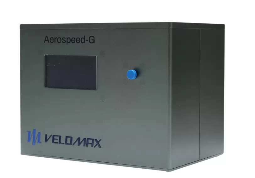
VeloMax Aerospeed-GS manual programmer.
9.3 AST-9000 and AST-1000: Automated Programming for Production
As production volume increases, manufacturers need programming equipment that can handle multiple devices in a controlled and repeatable workflow.
The AST-9000 is VeloMax's high-density automated IC programming system. According to VeloMax, it supports UFS, eMMC, and NAND/NOR Flash device types and integrates automated programming, inspection, marking, and packaging functions for high-volume production.
The AST-1000 provides automated programming with production-line integration capabilities, including MES integration, for manufacturers that need programming data and traceability connected to their broader manufacturing systems.
Both systems can be evaluated according to programming capacity, device handling requirements, and production-line integration needs. For the full range, visit the VeloMax programming equipment and production solutions overview.
9.4 Matching Programming Equipment to Your Project
Before selecting a VeloMax solution, it is helpful to prepare the following information:
- Target UFS device model and generation.
- Package type and storage capacity.
- Required programming image size and file format.
- Whether LUN, boot, descriptor, attribute, flag, or RPMB operations are required.
- Expected daily or monthly programming volume.
- Required programming speed and verification procedures.
- Whether manual operation, offline batch programming, or automated production is preferred.
Providing these details allows the equipment supplier to assess compatibility and recommend a solution based on actual application requirements. To learn more, visit the VeloMax official website or explore its programmer product range.
10. Conclusion
Understanding UFS storage architecture is essential for building a reliable programming workflow. The distinction between user LUNs and well-known logical units determines how images, boot data, and protected storage should be handled, boot-related settings influence device startup behavior, and RPMB introduces security requirements that must be handled carefully.
Descriptors, attributes, and flags provide additional information and configuration capabilities, while a structured workflow — including configuration commit and post-reset verification — helps engineers manage device detection, image programming, verification, and production traceability.
When selecting a UFS programmer, manufacturers should look beyond advertised speed and evaluate device compatibility, advanced configuration support, verification functions, production capacity, and technical support. The right equipment should match both current programming requirements and future manufacturing plans.
With its UFS programming products and broader semiconductor programming portfolio, VeloMax provides solutions for engineering and manufacturing teams seeking to improve programming efficiency and production consistency. Contact the team to discuss your target UFS devices and project requirements.


